
HRCC CONTINUOUS RO CONCENTRATION
HRCC Continuous High-Concentration Reverse Osmosis
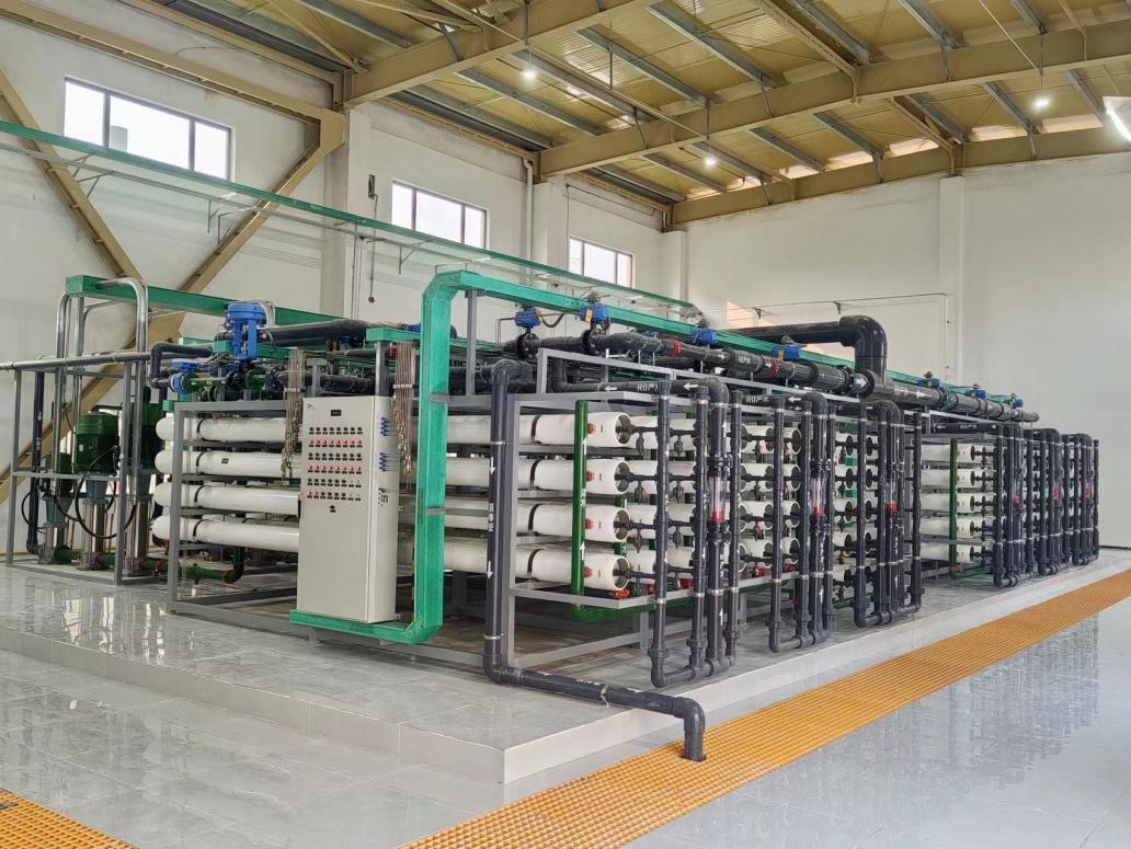
For suitably pretreated reuse water or brine, organize continuous RO permeate production and concentrate minimization through modular membrane groups, online operating-state changes, and a project-specific water balance, then connect the section to a downstream terminal process.
HRCC is not a universal concentration solution for every water or process fluid, and it does not replace front-end softening, organic control, evaporation and crystallization, or concentrate disposal.
APPLICATION FIT
First determine whether the feed supports continuous RO concentration
HRCC value depends on suitable pretreatment, modular operation, and a complete water balance. Equipment selection should not begin while scaling, fouling, or the concentrate endpoint remains undefined.
PRETREATMENT GATES
Front-end conditions determine whether HRCC belongs in the route
Continuous concentration does not eliminate contaminants; it changes water volume and concentration. Risks that will be amplified must be controlled before HRCC.
Particles & colloids
Confirm that SS, turbidity, colloids, and filtration boundaries are suitable for RO feed.
Scaling components
Control concentration risk through project-specific softening, silica removal, or other measures.
Organics & oil
Review COD/TOC, oil, surfactants, and biological fouling risks.
Chemistry & materials
Confirm pH, temperature, oxidants, solvents, and membrane-material compatibility.
Terminal-process compatibility
Confirm that the higher-concentration side stream can enter the downstream process or be managed appropriately.
Representative connection:Conditioning / PEK tubular membrane solids separation where required → protective filtration → HRCC RO → permeate reuse + concentrate terminal interface.
MODULAR OPERATING ARCHITECTURE
Organize continuous operation with a modular array and online operating-state changes
This page explains operating logic without publishing a fixed module count, turndown range, or universal concentration factor. Flow, pressure, feed quality, and cleaning strategy define the actual architecture.
Feed distribution
Distribute feed to suitable membrane groups according to operating state.
Module operation
Produce permeate continuously within the project-defined pressure, flow, and feed-quality window.
Online state change
Adjust module status around cleaning, maintenance, and load changes.
Process monitoring
Track pressure, flow, conductivity, and fouling trends to support operating decisions.
WATER BALANCE
HRCC design starts with a complete water balance and concentrate endpoint
Equipment feed and permeate alone are insufficient to assess engineering value. Pretreatment losses, cleaning waste, permeate use, and the concentrate endpoint all belong in the project boundary.
Average, peak, and variation
After sludge, backwash, and side streams
Module, pressure, and cleaning logic
Reuse or downstream use requires validation
Terminal process or disposal interface
This page does not provide a universal recovery, concentration factor, or minimization ratio. Project feed quality, pressure boundaries, and endpoints jointly determine these values.
QUALITATIVE ENGINEERING COMPARISON
HRCC differs from fixed-stage RO in operating organization, not by an absolute superiority claim
Both architectures require suitable membrane feed. Selection should compare feed quality, loading, cleaning, redundancy, control complexity, and complete-process interfaces.
Comparison dimension
Conventional fixed-stage RO
HRCC continuous concentration architecture
Operating organization
Operates with a defined staging and recovery relationship
Uses a project-specific modular array and online operating-state changes
Load variation
Typically adjusts around a fixed design point or limited range
Adapts around module status, flow, and a project-specific control strategy
Cleaning & maintenance
Uses sectional shutdown or another project-defined arrangement
Can incorporate module changeover and maintenance logic in the architecture
Application prerequisite
Meets the relevant RO feed and concentration boundaries
Also requires strict pretreatment and a defined concentrate endpoint
PROJECT EVIDENCE
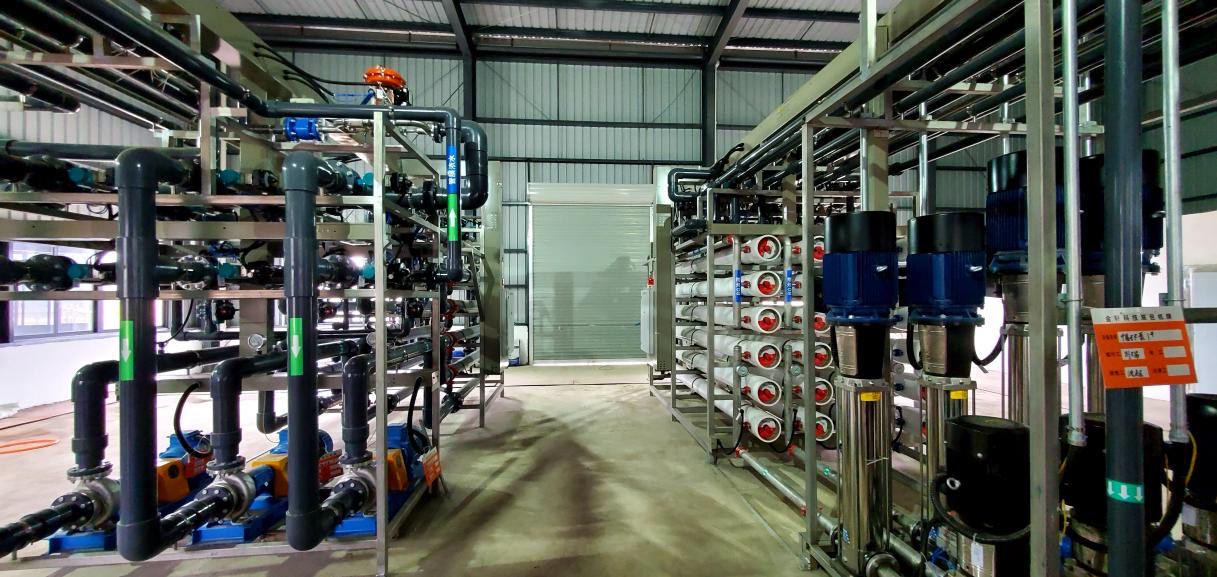
52 m³/h Anonymous power-plant cooling-tower blowdown projectEngineering record combining PEK pretreatment and HRCC RO
The project used softening conditioning, PEK tubular membranes, and an HRCC RO section. Public information is limited to capacity, feed type, and the technology combination; recovery, concentration factor, energy use, and operating performance are not disclosed.
ENGINEERING BOUNDARY
HRCC covers the continuous RO concentration section, not the complete ZLD terminal process
Plum can support pretreatment-interface assessment, the HRCC membrane section, and integrated membrane systems. Evaporation and crystallization, salt products, and final disposal are confirmed within the complete project scope.
PLUM can support
- Feed-fit and preliminary concentration-route review
- Membrane selection, module architecture, water balance, and cleaning strategy
- Integrated HRCC membrane system, instrumentation, controls, and CIP
- Commissioning, training, and upstream/downstream engineering interface support
Confirmed per project
- Front-end softening, oil removal, organic control, and biological treatment
- Evaporation and crystallization, salt products, and mother-liquor management
- Concentrate resource recovery or final disposal
- Civil works, utilities, and plant-wide performance responsibility
ENGINEERING FAQ
HRCC continuous concentration frequently asked questions
Suitability assessment should center on pretreatment gates, the water balance, and the concentrate endpoint.
Is HRCC suitable for every RO brine?
No. Review scaling, colloids, organics, oil, biological fouling, salt composition, osmotic pressure, temperature, and the concentrate endpoint before determining whether continuous concentration is feasible.
Can HRCC replace front-end softening or PEK tubular membranes?
No. Softening and PEK solids separation control scaling and fouling risks that intensify during RO concentration. Their use depends on the specific feed.
Is HRCC a complete ZLD system?
No. HRCC is a continuous RO concentration membrane section. Downstream evaporation and crystallization, salt products, mother liquor, and final disposal still require project-specific definition.
How is HRCC related to conventional RO?
Both use RO separation and require suitable feed. HRCC differs primarily through modular operation, online operating-state changes, and the way continuous concentration is organized.
Can recovery or concentration factor be promised directly?
No. Results depend on feed salt composition, fouling and scaling, pressure boundaries, temperature, pretreatment, permeate use, and the concentrate endpoint, and require project calculations and validation.
Why must the concentrate endpoint be defined first?
Concentration raises the level of some components. If downstream evaporation, crystallization, recycle, or disposal cannot accept that stream, increasing membrane concentration alone has no complete engineering value.
What information is required for a preliminary assessment?
Provide flow and variation, temperature, pH, TDS and complete ions, hardness, silica, alkalinity, SS, COD/TOC, oil, current pretreatment and RO operating records, permeate use, and the concentrate endpoint.
HRCC CONCENTRATION EVALUATION
Submit feed quality, water balance, and concentrate endpoint
Provide complete ion and contaminant analysis, current pretreatment and RO operating data, permeate use, and the final concentrate destination to assess HRCC suitability.
Submitted information is used only for preliminary route assessment and does not constitute a commitment on recovery, concentration factor, energy use, footprint, or continuous-operating metrics.