
COOLING BLOWDOWN · MINIMIZATION & REUSE
Cooling Blowdown Minimization & Reuse Engineering Route
Start with the cooling-water concentration regime, water-quality risks, and planned reuse point to determine how conditioning, PEK tubular membrane, RO, or HRCC sections should be combined, while including sludge, membrane concentrate, and the final concentrated side stream in one water balance.
The required process sections change with the cooling-water regime, chemicals, water quality, reuse point, and concentrate endpoint. This page does not substitute universal recovery or permeate values for project-specific assessment.
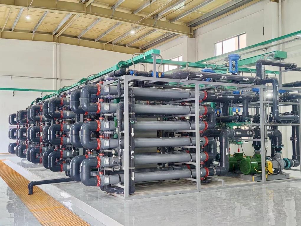
SYSTEM SCREENING
Define the cooling-water system before discussing the reuse route
Cooling blowdown, conventional reclaimed water, and RO brine have different origins and risks. Preliminary assessment first confirms where the water comes from, why it is discharged, and where it is intended to return.
Makeup and water sources
Confirm the original makeup source, process carryover, mixed water sources, and water-quality variation.
Recirculation and evaporative concentration
Review recirculation, makeup, and blowdown flows together with the actual operating regime.
Temperature and seasonal variation
Identify how load, climate, shutdown, and startup changes affect water quality and membrane sections.
Chemicals and water-quality risks
Review antiscalants, corrosion inhibitors, biocides, and other cooling-water chemicals.
Reuse point
Define whether water returns as cooling makeup, enters another process-water reuse point, or proceeds to further concentration.
Concentrate and engineering boundaries
Define the final destinations for sludge, membrane concentrate, final concentrate, and owner interfaces.
WATER QUALITY & OPERATING INPUTS
Assess scaling, corrosion, and fouling risks together
Evaporative concentration changes the relative levels of ions, organics, and treatment chemicals, but not every cooling blowdown stream is the same high-hardness, high-silica, or high-salinity wastewater. Every parameter requires actual analysis.
Hardness, silica, alkalinity, calcium, magnesium, and other potentially depositing species.
TDS or conductivity, chloride, sulfate, pH, and temperature.
SS, turbidity, COD/TOC, oil, and potential biological or colloidal risks.
Names, dosage, and residual effects of antiscalants, corrosion inhibitors, biocides, and other chemicals.
Average and peak blowdown flows, continuous or intermittent operation, seasonality, and load variation.
Reuse standard, reuse point, and final destinations for sludge and every concentrate stream.
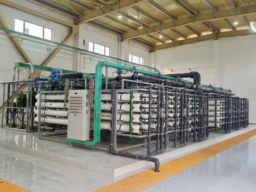
MODULAR PROCESS ROUTE
Combine process sections by risk and reuse objective; do not assume every section
Oil removal, organic control, softening, RO, and HRCC are project-selected modules. No section can promise the complete outcome independently of upstream and downstream interfaces.
- 01Collection and equalizationBalance flow, temperature, and periodic blowdown variation
- 02Oil / organic control where requiredConfigure against actual oil form and organic-fouling risk
- 03Project-specific conditioningConvert the scaling species that require control
- 04PEK tubular membraneSeparate reaction solids and retainable suspended matter
- 05pH readjustment and downstream protectionEstablish suitable conditions for downstream desalination or reuse
- 06RO or HRCCProvide desalinated reuse water or further concentration where water quality is suitable
- 07Reuse and side-stream endpointsConfirm permeate, sludge, and concentrate destinations separately
The PEK tubular membrane does not directly remove dissolved salts. RO or HRCC also cannot form a complete route without compatible pretreatment and a defined concentrate endpoint.
WATER BALANCE & REUSE DESTINATIONS
Close the destination of every stream before defining minimization and reuse
This page explains the method for establishing the water balance. Project recovery, concentration level, and blowdown reduction must be calculated from actual water quality, equipment boundaries, and final endpoints.
From original blowdown to the project-defined reuse point
- Original blowdownAverage flow, peak flow, and variation
- PEK membrane permeateAssess for downstream treatment or direct reuse
- RO / HRCC permeateSet against the target water quality
- Reuse endpointCooling makeup, process-water reuse, or another interface
TECHNOLOGY RESPONSIBILITIES
Each technology section addresses only its defined duty
Clear technology responsibilities prevent front-end solids separation, desalinated reuse, and the concentration endpoint from being combined into one performance promise.
Chemical conditioning
Convert target scaling species and form separable solids.
PEK tubular membrane
Provide continuous solids separation for reaction solids, suspended matter, and retainable contaminants.
RO desalination and reuse
Provide project-defined desalinated permeate where feed conditions are compatible.
HRCC concentration
Provide further concentration and volume reduction where pretreatment and water quality are suitable.
ENGINEERING CONTROL & BOUNDARY
Confirm cooling-system operation and membrane-system interfaces separately
Reaction conditions, materials, and cleaning strategy must match the actual ions and temperature.
For oily or high-organic streams, confirm oil form and upstream control responsibility first.
Cooling-water chemicals may affect reaction, fouling, and cleaning recovery and must be included in validation.
Summer and winter conditions, load, shutdown, and startup variation become design inputs.
Confirm cleaning media, recovery conditions, and cleaning-waste destination item by item.
Project risk determines bypasses, standby capacity, online instrumentation, and abnormal-condition handling.
Plum can support
- Water-quality and cooling-regime analysis, route screening, and water balance
- Project-specific design of softening, tubular membrane, RO, or HRCC sections
- Packaged membrane systems, required validation, commissioning, and engineering-interface support
Confirm per project
- Cooling-tower operation, cooling-water chemical program, and process-side responsibilities
- Civil works, utilities, and terminal destinations for sludge and concentrate
- Plant-wide recovery, reuse-water standard, operating cost, and total-system guarantees
PROJECT EVIDENCE
Two cooling blowdown project records
Only confirmed project capacities, feed types, and relevant engineering sections are published. Customer, location, year, permeate quality, and recovery performance are not shown.
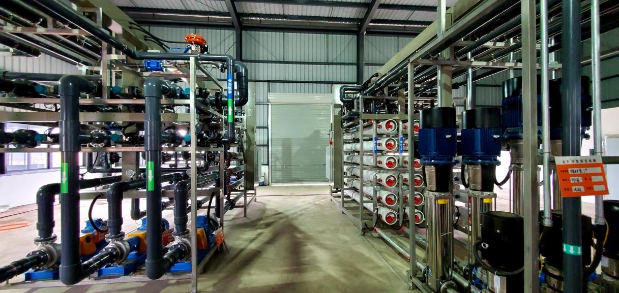
Anonymous project record 01
Power-plant cooling blowdown minimization and reuse
- Feed type
- Power-plant cooling blowdown
- Relevant engineering sections
- Conditioning + PEK tubular membrane + HRCC RO
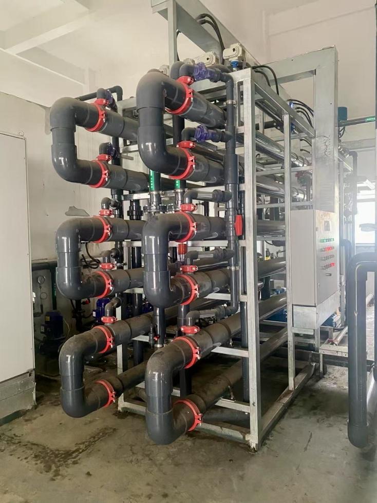
Anonymous project record 02
Biomass power-plant cooling blowdown reuse pretreatment
- Feed type
- Biomass power-plant cooling blowdown
- Relevant engineering sections
- Conditioning + PEK tubular membrane
Project capacities document relevant engineering experience only. They do not establish application fit, treatment performance, scope of supply, or guarantee values for a new project.
PROJECT RESOURCES
Prepare a cooling-blowdown project review
Business overviewIndustrial Water Reuse, Minimization & ZLD
Pretreatment routePEK Softening Process Package
ENGINEERING FAQ
Cooling blowdown minimization and reuse FAQ
The answers are present directly in the page HTML so engineers, search engines, and AI systems can understand the route boundaries.
How does cooling blowdown differ from RO brine?
Cooling blowdown comes from a recirculating cooling system and is shaped by makeup water, evaporation, the blowdown regime, and treatment chemicals. RO brine comes from the reverse-osmosis concentrate side and has a different ion and contaminant concentration mechanism. Both may occur in one project, but they cannot use the same pretreatment and reuse route by default.
Is softening always required before cooling blowdown reuse?
No. Softening depends on hardness, silica, alkalinity, the reuse point, downstream membrane sections, and the concentration endpoint. Use conditioning and solids separation only where scaling risk and the reaction route justify them.
Can a PEK tubular membrane directly remove dissolved salts?
No. The PEK tubular membrane mainly separates reaction solids, suspended matter, and retainable contaminants. Dissolved-salt control normally requires RO, NF, or another compatible desalination or concentration section.
Must every project use HRCC?
No. HRCC is an optional concentration section where pretreatment and water quality are compatible. If the reuse objective, concentrate endpoint, or water quality is unsuitable, use another route and close the water balance again.
Where can treated water be reused?
It may return as cooling-system makeup, serve another process-water reuse point, or enter another membrane section. Permeate quality, cooling-water control standards, process responsibility, and the water balance jointly determine the actual reuse point.
What information is required for preliminary assessment?
Provide makeup-water and blowdown analyses, recirculation and blowdown flows, temperature and seasonal variation, the cooling-water chemical list, existing treatment, reuse point, target standard, and final destinations for sludge and every concentrate stream.
SUBMIT COOLING BLOWDOWN DUTY
Submit the cooling-water regime and water-quality data for preliminary route assessment
Describe makeup water, recirculation and blowdown flows, water quality, chemicals, existing treatment, planned reuse point, and concentrate endpoint. Plum will use this information to review data completeness, primary risks, and process boundaries requiring further validation.
Submitted information is used only for preliminary route assessment. It does not constitute a commitment on recovery, permeate quality, concentration level, chemical consumption, operating cost, equipment configuration, or complete project scope.