FGD WASTEWATER MINIMIZATION & ZLD
FGD Wastewater Minimization & ZLD Engineering Routes
Start with the wet-FGD wastewater discharge point, suspended solids, and scaling ions, then assess chemical conditioning, PEK tubular membrane solids separation, membrane concentration where required, and evaporation, crystallization, or other terminal interfaces.
This page supports preliminary engineering route screening. The process combination changes with the FGD system, discharge point, actual water quality, and final solids destination.
Confirm whether the feed is absorber blowdown, existing pretreatment effluent, or a mixture of terminal wastewater streams.
Identify gypsum, hardness, metals, and other reaction solids, then define sludge and recycle boundaries.
Assess membrane concentration together with evaporation and crystallization, flue-gas evaporation, solidification, or compliant-disposition interfaces.
FEED WATER RISK PROFILE
FGD wastewater is not one fixed water quality
Coal type, limestone quality, absorber operation, chloride control, oxidation method, makeup-water source, and existing chemical-treatment units all affect the final wastewater composition. The following items require project-specific analysis.
Confirm the actual discharge point associated with absorber slurry, gypsum dewatering, and chloride control.
Assess residual risks after neutralization, precipitation, flocculation, clarification, or filtration.
Where FGD wastewater is combined with other power-plant streams, re-establish the water, quality, and solids balances.
- Suspended solids and gypsum fines
- Particle concentration, size, settling behavior, and crystal form affect reaction-solids separation, sludge dewatering, and downstream membrane fouling.
- Calcium, magnesium, and scaling tendency
- Assess alkalinity, sulfate, silica, temperature, and concentration factor together when defining softening reactions and downstream scaling risk.
- Chloride, sulfate, and TDS
- Ionic composition affects corrosion and osmotic pressure and also determines whether salt fractionation, concentration, and evaporation or crystallization routes are viable.
- Metals and trace constituents
- Arsenic, selenium, mercury, cadmium, and other metals do not occur at the same concentrations in every project. Confirm them by analysis, species, and disposition objective.
- Silica, organics, and additives
- Total silica, COD/TOC, antifoam, scale inhibitors, and other FGD additives may affect reactions, membrane fouling, and cleaning boundaries.
- pH, temperature, and flow variability
- Starts, stops, load changes, and the discharge schedule change instantaneous conditions. Equalization volume and control strategy must be based on historical data.
Engineering principleThe typical constituents listed on this page establish an analysis checklist only. They do not replace a project water-analysis report or support direct commitments on removal, recovery, or final salt quality.
ROUTE SCREENING
Close five engineering questions before discussing equipment
An FGD wastewater route should not begin with an equipment list. Define system boundaries, chemical species, and final destinations before assessing tubular membrane, NF, RO, HRCC, or evaporation sections.
- 01Discharge point and flowSource, average and peak flow, discharge schedule, load, and seasonal variability
- 02Composition and solids formDissolved salts, suspended solids, gypsum, metal precipitates, and chemical effects
- 03Treatment objectiveStable pretreatment, reuse, minimization, salt fractionation, resource recovery, or ZLD
- 04Concentrate and sludge endpointsRecycle, dewatering, evaporation and crystallization, flue-gas evaporation, solidification, or disposition
- 05Plant-wide interfacesFGD system, chemicals, utilities, controls, EPC interfaces, and final guarantee boundaries
Stable pretreatment
Establish continuous conditioning and solids separation for reaction solids, suspended solids, hardness, metals, or silica to provide stable feed to downstream treatment.
Membrane minimization and salt-fractionation assessment
Where water quality and project objectives are compatible, assess selectivity, concentration boundaries, and cleaning conditions for NF, RO, HRCC, or related membrane sections.
ZLD terminal integration
Confirm membrane concentrate, mother liquor, sludge, salts, and evaporation, crystallization, or another endpoint within one water and salt balance.
MODULAR PROCESS ROUTE
Control solids first, then connect concentration and terminal sections as required
The following route identifies engineering sections for assessment. It does not mean every FGD wastewater project requires the complete chain. Project data determine reaction stages, membrane combinations, recycle, and terminal sections.
- 01Wastewater collection and equalization
Isolate abnormal feeds and buffer flow, pH, temperature, and water-quality variability.
- 02Oxidation / neutralization / chemical conditioning
Define reaction conditions against metals, hardness, sulfate, silica, and other target species.
- 03Precipitation and flocculation
Convert target constituents into separable solids and confirm sludge properties.
- 04PEK tubular membrane solids separation
Continuously retain reaction solids and fine particles to provide stable clarified liquid to downstream membrane or terminal sections.
- 05Salt fractionation / desalination / concentration as required
Assess selective NF, RO, HRCC, or another concentration section only where water quality is suitable.
- 06Evaporation, crystallization, or another endpoint
Confirm evaporation, crystallization, flue-gas evaporation, solidification, and salt or solid-waste destinations per project.
Sludge thickening, dewatering, filtrate recycle, and final solid-waste responsibility must be closed separately.
Recycle location, impurity accumulation, crystallized-salt objectives, and mother-liquor endpoints cannot be default assumptions.
Not a fixed route:If feed composition or terminal conditions do not suit a membrane section, adjust, replace, or remove that section instead of retaining it merely to present a complete route.
TECHNOLOGY RESPONSIBILITIES
Each section performs only a verifiable duty
Separate reaction removal, solids separation, dissolved-salt separation, and final solidification to avoid presenting one device as the outcome of the complete ZLD route.
Chemical conditioning and species conversion
Convert hardness, metals, sulfate, silica, or other target constituents into separable solids according to project objectives. Water analysis and testing determine chemicals and reaction conditions.
PEK tubular membrane
Provide continuous cross-flow separation of reaction solids, fine particles, and suspended solids. The membrane does not directly remove dissolved chloride or all TDS.
View PEK softening and solids separation → 03 · SELECTIVE SEPARATIONSelective nanofiltration
Assess salt fractionation or impurity control only where ionic composition, target products, and membrane selectivity are compatible. It is not a default FGD wastewater configuration.
View selective nanofiltration technology → 04 · CONCENTRATIONHRCC / other concentration sections
Use for concentrate minimization where pretreatment, osmotic pressure, and other boundaries are suitable. The achievable concentration endpoint and recovery are project-specific.
View HRCC technology →FOUR INTERFACES TO CLOSE
Close four interfaces in every FGD wastewater project
Membrane-system stability is only one part. If upstream FGD operation, solid by-products, concentrate recycle, or final disposition is unclear, the basis for the complete route may fail.
FGD system and discharge schedule
Confirm absorber chloride control, gypsum dewatering, oxidation, makeup water, and the discharge schedule, and define which variations remain upstream responsibilities.
Reaction sludge and dewatering filtrate
Confirm sludge quantity and properties, thickening and dewatering, filtrate recycle, and final solid-waste destination to prevent contaminant reaccumulation.
Membrane concentrate and mother-liquor management
Confirm composition, flow, recycle location, and impurity-enrichment boundaries for each concentrate stream. Recycle does not make contaminants disappear.
Evaporation, crystallization, or another endpoint
Confirm evaporator or crystallizer feed, salt or solids requirements, utilities, corrosion-resistant materials, and final-disposition responsibility.
DESIGN INPUTS
Minimum information for preliminary assessment
- System and flow
- FGD process, discharge point, average and peak flow, operating hours, and historical variability
- Basic water quality
- Temperature, pH, SS, turbidity, TDS, conductivity, COD/TOC, and alkalinity
- Ionic composition
- Ca, Mg, Na, Cl, SO4, silica, and the complete cation-anion balance
- Metals and additives
- Target metals, scale inhibitors, antifoam, flocculants, and other FGD chemicals
- Existing facilities
- Existing chemical treatment, clarification, filtration, sludge dewatering, reuse, evaporation, and control systems
- Project endpoints
- Reuse requirements, minimization target, evaporation interface, salt or solids destinations, and responsibility boundaries
- Review of water quality, flow, and existing-system information
- Route design for chemical conditioning and tubular membrane solids separation
- Selection and packaged supply of NF, RO, HRCC, and related membrane sections where required
- Sample testing, pilot validation, scale-up, and commissioning support
- Membrane-section controls, CIP, and owner or EPC interface support
- FGD absorber, gypsum dewatering, and upstream operating responsibility
- Civil works, utilities, chemical storage and handling, and sludge-dewatering facilities
- Evaporation and crystallization, flue-gas evaporation, solidification, and corrosion-material boundaries
- Final destinations of salt products, sludge, mother liquor, and other solids
- Plant-wide water and salt balance, total-system performance, and turnkey responsibility
EVIDENCE BEFORE PROMISE
Build project design inputs through three evidence levels
The public page does not publish customer names, project capacities, dates, recovery, hardness removal, salt-fractionation ratios, or salt quality without separate approval.
- 01 · PUBLIC ENGINEERING FACT
Installed systems and engineering sections
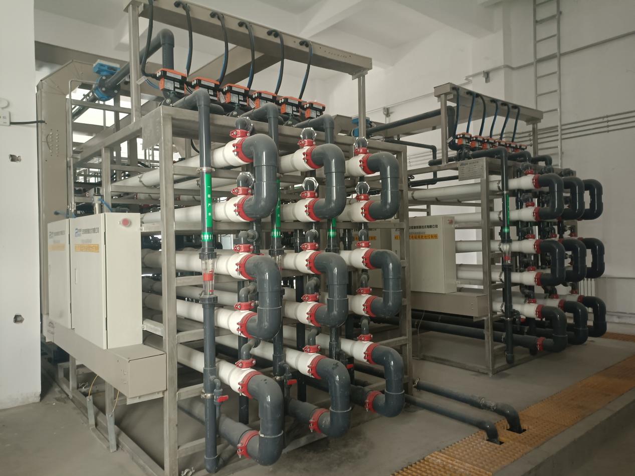
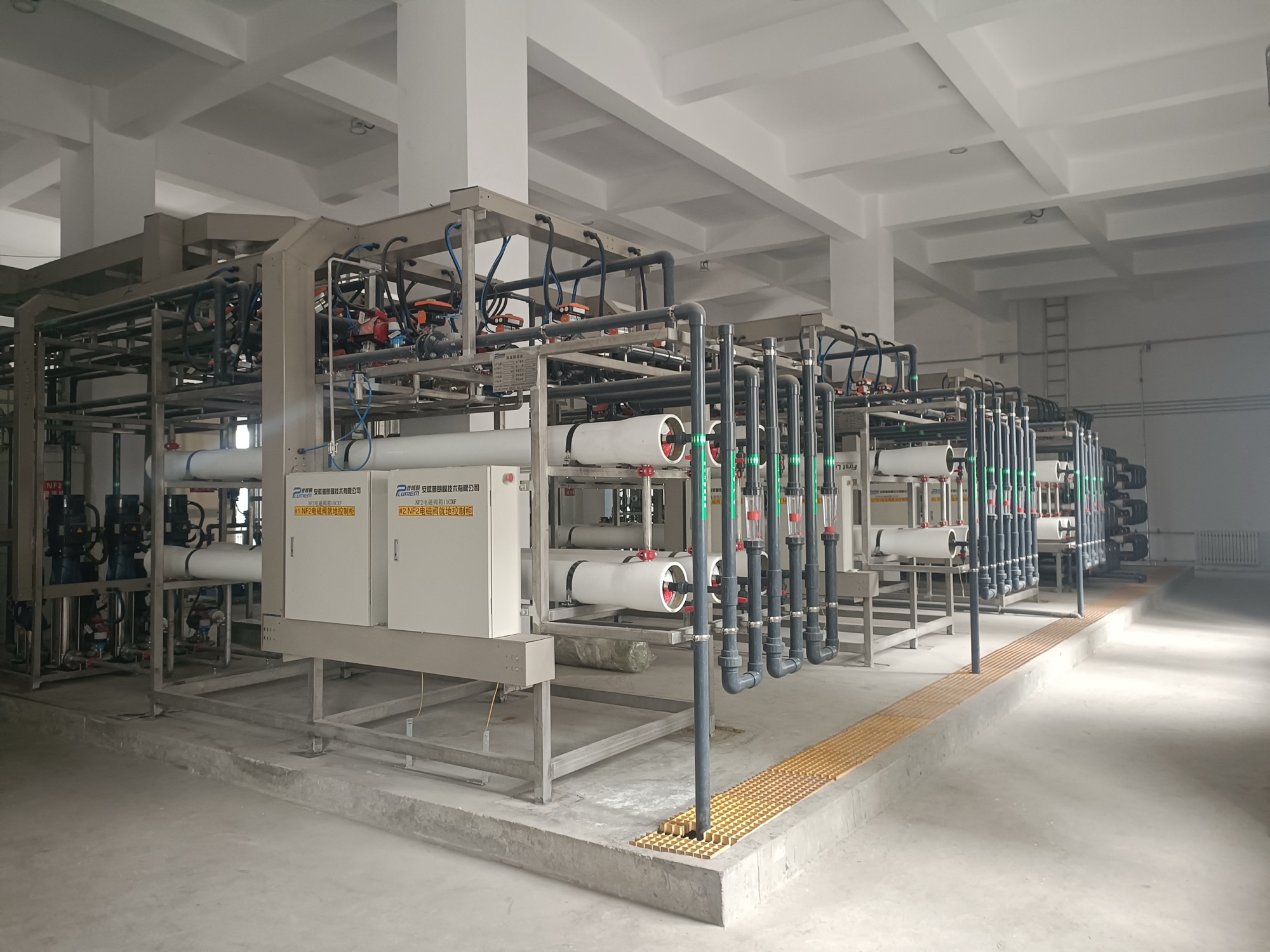
Public system photographs and engineering facts for chemical conditioning, tubular membrane solids separation, downstream membrane sections, and terminal interfaces.
- 02 · TRANSFERABLE PROCESS BASIS
Related technologies and high-salinity project experience
PEK softening, selective NF, and concentration technologies can inform route development, but performance in another industry does not become an FGD wastewater guarantee.
- 03 · PROJECT-SPECIFIC PROOF
Sample testing, pilot validation, and formal design
Use actual water samples, continuous operation, and a complete water and salt balance to establish reaction conditions, membrane suitability, fouling and cleaning behavior, and scale-up inputs.
SAMPLE & PILOT VALIDATION
Validate before scale-up when ionic composition, metal species, or concentration boundaries are unclear
PROJECT RESOURCES
Prepare FGD wastewater project information
Route overviewIndustrial wastewater reuse, minimization & ZLD
Upstream processPEK softening and solids separation
ENGINEERING FAQ
FGD wastewater route frequently asked questions
Why can one fixed route not be applied to all FGD wastewater?
FGD process, coal type, limestone quality, discharge point, existing pretreatment, chloride control, and final-disposition boundaries all change water quality and the water and salt balance. Route screening must begin with actual project data.
Can a PEK tubular membrane directly remove chloride and TDS?
No. The tubular membrane primarily separates reaction solids, gypsum fines, and suspended solids. Dissolved salts require suitable NF, RO, concentration, or thermal terminal treatment.
Does every FGD wastewater project require softening?
No. The need for softening, its target, and reaction stages depend on calcium, magnesium, sulfate, silica, alkalinity, downstream membrane sections, and evaporator requirements. Confirm them through water-quality calculations and testing.
Is selective-NF salt fractionation mandatory for FGD wastewater ZLD?
No. Assess salt fractionation only where ionic composition, target products, membrane selectivity, and the downstream crystallization route are compatible. Otherwise, modify or remove the membrane section.
Does Plum always supply the evaporation and crystallization system for ZLD?
No. Plum can support membrane-process sections and engineering interfaces. Evaporation and crystallization, flue-gas evaporation, solidification, salt products, and solid-waste disposition must be confirmed separately in the project contract.
When is sample testing or pilot validation recommended?
Start with testing where metal and silica species are unclear, chemical effects are complex, salt fractionation or high concentration requires validation, comparable water-quality data are unavailable, or continuous-operation and cleaning boundaries must be established. Use pilot validation as required.
What core information is required for preliminary assessment?
Provide at least the FGD process and discharge point, average and peak flow, complete water analysis and ion balance, metals and additives, existing process, water balance, treatment objectives, concentrate, sludge, and salt endpoints, and available process diagrams and historical operating data.
Can old project records or brochure data be used directly as new-project guarantees?
No. Existing project records, test data, and new-project guarantee values have different conditions of applicability. Formal values require separate confirmation through data review, necessary validation, and the technical agreement.
SUBMIT FGD WASTEWATER DUTY
Submit FGD wastewater duty for a preliminary route assessment
Provide the FGD process, discharge point, complete water analysis and water balance, existing treatment, objectives, and sludge, concentrate, salt, and solids destinations. Plum will first review data completeness and then identify the engineering sections that can be assessed.
Submitted information is used only for preliminary project assessment. It does not constitute a commitment on removal, recovery, salt-fractionation performance, salt quality, energy use, scope of supply, or delivery schedule.