APPLICATION FIT
Identify oil form and emulsion stability before selecting a tubular membrane route
Oily wastewater is not one uniform duty. Free oil, dispersed oil, emulsified oil, and organics truly dissolved in water require different treatment functions. Tubular membranes primarily separate oil droplets, colloids, and suspended solids that match the membrane retention boundary.
Suitable for initial assessment
Further confirmation required
- Fractions, droplet sizes, sampling methods, and analytical methods for free oil, dispersed oil, emulsified oil, and dissolved organics
- Surfactants, demulsifiers, solvents, polymers, microorganisms, and other emulsion-stabilizing factors
- Variation in flow, temperature, pH, salinity, viscosity, COD, SS, and oil loading
- Reinjection, reuse, discharge, or downstream membrane objective, plus destinations for concentrate, float sludge, and oily sludge
- Oil form
- Fractions, droplet sizes, and stabilizing factors for free, dispersed, emulsified, and dissolved components
- Feed conditions
- Flow, temperature, pH, salinity, viscosity, COD, SS, polymers, and solvents
- Treatment endpoint
- Reinjection, process reuse, NF/RO protection, polishing, or the project-defined discharge interface
- Concentrate boundary
- Float sludge, membrane concentrate, oily sludge, dewatering filtrate, and recycle paths
PROCESS ROUTE
Integrate upstream oil removal, tubular membrane separation, and the downstream endpoint
The following is a base engineering logic. The need for gravity separation, coalescence, flotation, demulsification, a particular membrane specification, and downstream treatment depends on oil-droplet form, water chemistry, and final use; equipment cannot be selected from total oil alone.
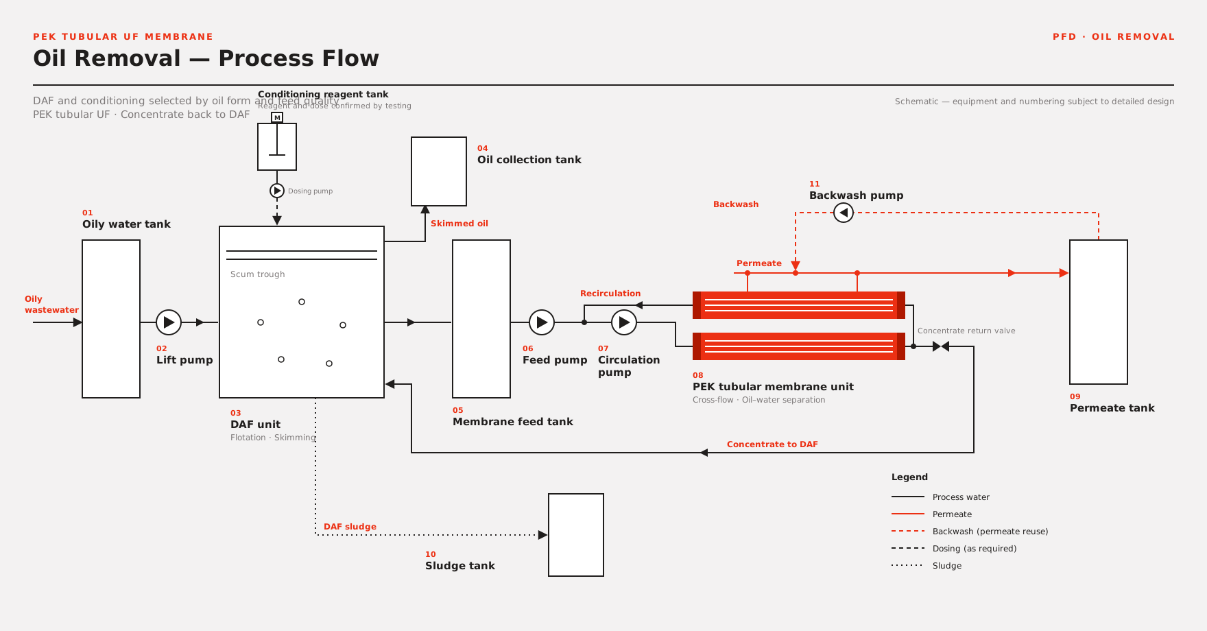
View the crawlable text process route
- 01 – Segregated collection and equalization – Segregate high-oil, solvent-bearing, or abnormal batches and stabilize flow, temperature, oil loading, salinity, and suspended solids to protect downstream units.
- 02 – Remove free oil upstream as required – Apply gravity separation, coalescence, coarse filtration, demulsification, or dissolved-air flotation according to droplet size and emulsification, removing economically separable oil and coarse particles first.
- 03 – PEK tubular membrane cross-flow separation – The tubular membrane loop retains emulsified oil droplets, colloids, and suspended solids matching the membrane specification. Permeate and concentrate then enter their respective downstream boundaries.
- 04 – Route permeate to the project endpoint – Connect permeate to biological treatment, adsorption, oxidation, NF/RO, desalination, or other polishing according to the reinjection, reuse, or discharge objective; membrane permeate is not assumed to be the final endpoint.
- 05 – Close the concentrate and oily-sludge loop – Route membrane concentrate, float sludge, and oily sludge to concentration, dewatering, recovery, or compliant disposal. Confirm filtrate recycle and plant-wide recovery by mass balance.
Core engineering principle:Upstream units preferentially remove larger droplets and floatable oil; the tubular membrane performs finer oil-droplet and solids separation; truly dissolved organics require a matching downstream process. These three duties must not be represented as one oil-removal rate.

OIL FORM & SEPARATION DUTIES
Separate oil-droplet retention from dissolved-organic treatment
Tubular membrane suitability depends not only on the amount of oil, but also on its form, droplet stability, the effect of surfactants at the membrane surface, and the required destination of the permeate.
- Free oil
- Larger, floatable oil is normally removed first by gravity separation, coalescence, or flotation to reduce membrane loading and oily-sludge recycle.
- Dispersed and emulsified oil
- Where oil droplets, colloids, and solids match the membrane retention boundary, PEK tubular membrane cross-flow separation can be assessed, with demulsification or conditioning upstream where required.
- Dissolved organics
- Hydrocarbons and small organic molecules truly dissolved in water may pass through ultrafiltration and require adsorption, oxidation, biological treatment, NF/RO, or other polishing selected for the objective.
- Fouling and cleaning
- Surfactants, polymers, solvents, viscosity, temperature, and salinity affect emulsion stability and membrane-surface behavior. Cleaning must be checked against both material compatibility and duty conditions.
For spent emulsions of unknown composition, solvent-rich or highly viscous feeds, and strongly stabilized emulsions, begin with sample screening and bench testing to confirm compatibility, retained species, flux, and cleaning recovery before scale-up.
ENGINEERING BOUNDARY
Separate brochure references, project records, and new-project guarantees
Public data helps determine whether a technical assessment is justified. It does not replace oil-form analysis, pretreatment selection, membrane-area design, or guarantee conditions for a new project. Case flux and effluent values must not be transferred directly to a different emulsion system.
PUBLISHED INLET / OUTLET REFERENCE
Published influent and effluent comparison
The six values below come from the existing oil-removal process-solution brochure and illustrate solution-level influent and effluent references for applicable designs. They are not single-membrane-section performance values and do not automatically become guarantees for a new project.
- Oil contentmg/L
- Influent reference<1000 →
- Outlet reference<5
- Published removal99.5%
- Suspended solidsmg/L
- Influent reference<1000 →
- Outlet reference<1
- Published removal99.9%
- Median particle sizeμm
- Influent reference<20 →
- Outlet reference<1
- Published removal—
- Sulfate-reducing bacteriacells/mL
- Influent reference<1000 →
- Outlet reference<10
- Published removal99%
- Saprophytic bacteriacells/mL
- Influent reference<10000 →
- Outlet reference<100
- Published removal99%
- Iron bacteriacells/mL
- Influent reference<10000 →
- Outlet reference<100
- Published removal99%
Removal rates are reproduced from the source brochure and are not recalculated here from limits marked with “<”. A formal project must define the solution boundary, influent and effluent sampling points, analytical methods, upstream flotation or pretreatment, stable operating period, and guarantee conditions.
How these references are used in project design
| Engineering item | Current public reference | Project-specific confirmation |
|---|---|---|
| Oil form | Public material covers free, emulsified, dispersed, and suspended oil | Analyze sampling method, droplet size, stability, surfactants, and dissolved components separately rather than relying on total oil alone |
| Project membrane flux | Public project records on this page range from 70 to 150 LMH | Applies only to the respective projects; new duties require confirmation against oil droplets, solids, polymers, viscosity, temperature, circulation, and cleaning tests |
| System recovery | No universal guarantee stated | Affected by flotation-sludge discharge, membrane concentration factor, oily-sludge dewatering, filtrate recycle, CIP discharge, and the plant-wide mass balance |
| Cleaning and compatibility | PEK tubular membranes are assessed for complex oily and high-fouling duties | Cleaning agents, solvents, surfactants, pH, temperature, shutdown preservation, and material compatibility require item-by-item confirmation |
Formal technical documents must define design influent, post-pretreatment membrane feed, oil analytical methods, design values, guarantee values, membrane flux, recovery, cleaning conditions, permeate endpoint, concentrated oily-sludge boundary, and exclusions.
PROCESS ROUTE SELECTION
Oil form, co-contaminants, and treatment endpoint determine the route together
Produced water, fracturing flowback, and machining emulsions are all oily streams, but their stabilization mechanisms, concentrate value, and downstream objectives differ. The three routes below may be combined but are not interchangeable.
Flotation / upstream oil removal + PEK tubular membrane
- Applicable feed
- Free oil is controlled, while emulsified droplets, colloids, and suspended solids remain under variable water conditions.
- Primary duty
- Upstream treatment reduces larger-droplet loading; the PEK tubular membrane performs continuous fine cross-flow separation.
- Downstream interface
- Permeate enters reinjection, reuse, downstream membrane treatment, or project-defined polishing.
High-salinity produced water + desalination / reuse
- Applicable feed
- Produced water or flowback also contains high salinity, polymers, hardness, silica, or dissolved COD.
- Primary duty
- Oil-removal and clarification sections protect NF/RO, softening, concentration, and other reuse or ZLD units.
- Decision basis
- Assess total salinity, scaling ions, dissolved organics, concentrate endpoint, and plant-wide recovery together.
Stable emulsions / solvent-bearing fluids
- Applicable feed
- Machining emulsions, degreasing or cleaning fluids, high-surfactant or high-viscosity feeds, and batches of unknown composition.
- Primary duty
- First confirm demulsification needs, membrane compatibility, retained species, cleaning recovery, and concentrate destination.
- Decision basis
- Use sample testing and pilot data where required to establish an operating window before selecting resource-recovery or wastewater-treatment routes.
When oily wastewater also contains high SS, hardness, silica, heavy metals, high COD, or a biological-treatment duty, combine routes according to contaminant form rather than assigning every treatment objective to one tubular membrane section.
SOLUTION SCOPE
Define pretreatment, membrane circulation, permeate endpoint, and oily-sludge destination separately
The following supports preliminary assessment and detailed design. It does not mean every project automatically includes flotation, demulsification chemicals, civil works, desalination, biological treatment, sludge dewatering, or responsibility for plant-wide discharge or reuse.
Core oil-removal and membrane section
- Design interfaces for equalization, upstream oil removal, and membrane-feed conditions
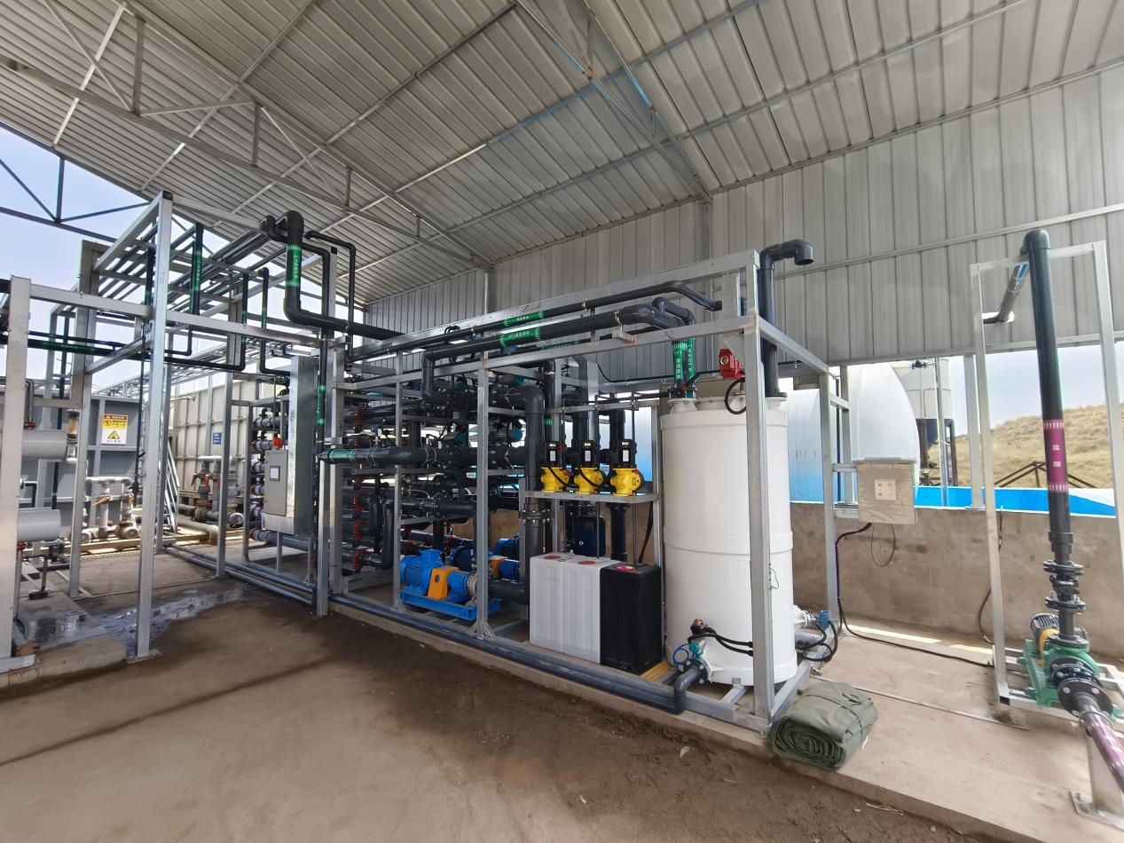
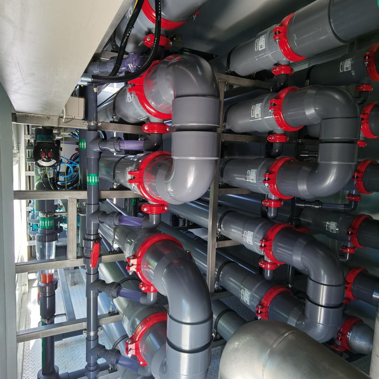
- PEK tubular membrane modules, rack, feed pump, and cross-flow circulation pumps
- Permeate, concentrate, CIP, pressure, flow, temperature, and level controls
Optional engineering scope
- Oil separation, coalescence, demulsification, dissolved-air flotation, coarse filtration, and conditioning chemical systems
- Oily-sludge concentration and dewatering, filtrate return, oil-phase recovery, and storage interfaces
- Biological treatment, adsorption, oxidation, NF/RO, softening, desalination, or ZLD units
Owner / EPC interfaces
- Segregated collection, civil tanks, building, site piping, and utilities
- Feed and permeate analysis, chemical supply, sludge classification, and final destination
- Installation and commissioning conditions, plant-wide interlocks, reinjection or reuse standards, and local compliance requirements
Final scope, pretreatment responsibility, membrane-separation guarantee, permeate endpoint, oily-sludge boundary, design responsibilities, and interface conditions follow the mutually approved technical and commercial documents.
APPLICATION ROUTES
Define applications by oil source, emulsification mechanism, and downstream use
The applications below can enter preliminary assessment, but cannot share one pretreatment, membrane flux, cleaning cycle, permeate specification, recovery, or oily-sludge disposal route.
Oilfield produced water
Review high salinity, emulsified oil, polymers, microorganisms, and reinjection or process-reuse objectives, combining gravity separation, flotation, tubular membranes, and desalination as required.
Fracturing flowback
For oil, suspended solids, high salinity, hardness, additives, and water variability, first define stream segregation, oil-removal clarification, and the downstream reuse or treatment endpoint.
Refining and storage wastewater
Configure upstream oil removal, membrane separation, biological treatment, and polishing interfaces against oil type, free/emulsified oil fractions, sulfides, and COD.
Machining emulsions
Review cutting oil, emulsifiers, metal fines, viscosity, and recovery value. Complex formulations should begin with sample testing.
Degreasing and oily cleaning wastewater
Assess surfactants, solvents, alkalinity, and batch variability, and define whether the objective is wastewater minimization, oil-phase recovery, or protection of downstream biological treatment.
Food-industry oily wastewater
For vegetable or animal oils, fats, proteins, and high COD, tubular membranes may be assessed for oil-droplet and solids separation, while biological treatment and sludge routes still require separate design.
PROJECT EVIDENCE
Support route screening with project records at different scales and endpoints
Customer names remain anonymous. Pretreatment, influent and effluent, membrane flux, and downstream use apply only to the stated projects and do not establish design values, guarantees, or treatment commitments for other oil systems.
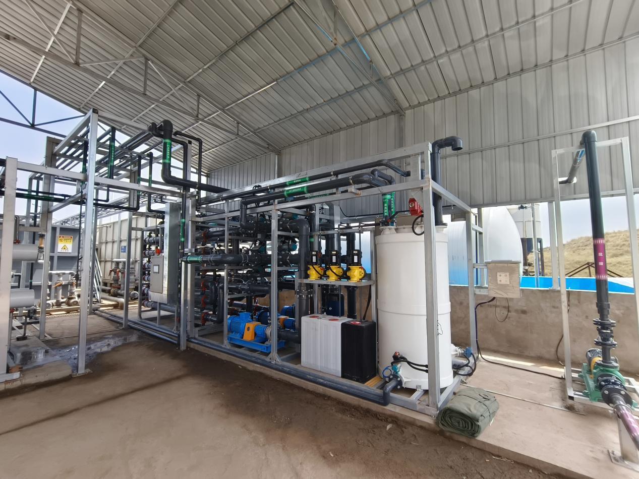
FRACTURING FLOWBACK · PUBLIC PROJECT RECORD
200 m³/d oil-removal clarification project at an anonymous Shaanxi oil and gas field
- Process
- Dissolved-air flotation + PEK tubular membrane
- Influent oil
- 10–50 mg/L
- Permeate oil
- ≤1 mg/L; this project record only
- Reference flux
- 70–100 LMH; commissioned in 2024

OILFIELD PRODUCED WATER · PUBLIC PROJECT RECORD
1,200 m³/d oil-removal and reuse project at an anonymous Shaanxi oilfield
- Process
- Dissolved-air flotation + PEK tubular membrane
- Influent oil
- 10–50 mg/L
- Permeate oil
- <1 mg/L; used to prepare fracturing fluid in this project
- Reference flux
- 70–80 LMH; commissioned in 2023
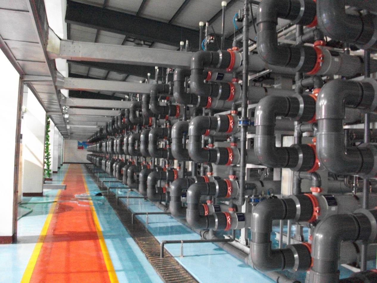
POLYMER-FLOOD PRODUCED WATER · PUBLIC PROJECT RECORD
10,000 m³/d polishing project at an anonymous Daqing oilfield
- Process
- Oil-water separation followed by tubular membrane + nanofiltration desalination
- Influent oil
- 50–100 mg/L
- Permeate oil
- ≤5 mg/L; applies only to this project-wide process
- Reference flux
- 100–150 LMH; commissioned in 2011
Project data comes from existing public material. Image-to-reference matching, complete process boundaries, sampling and oil-analysis methods, customer anonymization, image rights, and all quantitative values require review before formal publication.
RESOURCES
Selection resources and next steps
ProductPEK tubular membrane details
Public resourceTubular membrane brochure
Project preparationProject evaluation worksheet
TECHNICAL FAQ
Oil-removal process-solution frequently asked questions
Can a PEK tubular membrane directly remove every form of oil?
No. A tubular membrane primarily retains oil droplets, colloids, and suspended solids that match its specification. Larger free oil is normally removed first by gravity separation, coalescence, or flotation. Truly dissolved organics may pass through ultrafiltration and require other polishing.
How do free oil, dispersed oil, emulsified oil, and dissolved organics differ?
They differ in droplet size, stabilization mechanism, and separability. Free oil rises readily; dispersed oil exists as smaller droplets; emulsified oil is stabilized by surfactants or similar agents; dissolved organics exist at molecular scale. Selection must consider the analytical method and droplet size, not total oil alone.
Can oil separation, coalescence, or flotation be removed after adding tubular membranes?
Not universally. Removing larger droplets upstream is generally more economical and lowers membrane loading. The route may be simplified only where free oil is low, droplet size and water quality are stable, and direct membrane separation has been validated.
Can influent below 1,000 mg/L and effluent below 5 mg/L be used directly as guarantees?
No. These are public brochure screening references, and the value below 5 mg/L is explicitly limited to applicable designs. A formal guarantee requires defined membrane-feed sampling, oil form, analytical method, pretreatment, operating conditions, and permeate endpoint.
How are membrane concentrate and oily sludge handled, and how is water recovery determined?
Select recovery, concentration and dewatering, or compliant disposal according to oil-phase value, solids, chemicals, hazardous properties, and local requirements. Plant-wide recovery must include flotation-sludge discharge, oily-sludge moisture, filtrate recycle, membrane-concentrate discharge, and CIP waste.
What data is required for preliminary assessment?
Provide at least flow and operating hours, total oil and oil form, droplet-size or emulsion information, SS, COD, pH, temperature, salinity, viscosity, polymers, surfactants, solvents, existing process, target use, oily-sludge destination, and available cleaning conditions. Complex feeds should provide samples.
OIL REMOVAL PROJECT EVALUATION
Submit oil form and treatment endpoint for preliminary route assessment
Upload a complete water analysis, oil analysis, existing oil-separation or flotation process, and target use where possible. The engineering team will first assess pretreatment, tubular membrane duties, the need for sample validation, and interfaces to reinjection, reuse, NF/RO, or polishing.
Submitted information is used only for preliminary project assessment. Final pretreatment, membrane specification, membrane area, flux, recovery, permeate values, cleaning, oily-sludge route, scope, and guarantee conditions are defined in the formal technical documents.