APPLICATION FIT
Identify particle and colloid risks before selecting direct tubular membrane clarification
The suspended solids removal process solution serves industrial fluids requiring stable solids separation. The key question is not how turbid the water looks, but whether particle composition, size, concentration, viscosity, filterability, and downstream feed requirements match cross-flow tubular membranes.
Suitable for initial assessment
Further confirmation required
- Whether suspended solids are rigid particles, colloids, fibers, paint sludge, biological solids, or compressible sticky material
- Whether dissolved COD, salts, hardness, silica, heavy metals, or emulsified oil also require separate treatment
- pH, temperature, viscosity, oil and surfactants, oxidants, and acceptable chemical-cleaning window
- Permeate use, downstream equipment requirements, concentrate destination, and plant-wide water-recovery boundary
- Particle loading
- SS, turbidity, particle-size distribution, colloids, settling behavior, and variability
- Feed conditions
- Flow, temperature, pH, viscosity, oil, COD, salinity, and cleaning constraints
- Downstream objective
- Reuse, NF/RO protection, resource recovery, polishing, or discharge interface
- Concentrate boundary
- Recycle, concentration, dewatering, filtrate return, sludge discharge, or off-site handling conditions
PROCESS ROUTE
Close the loop across clarification, permeate routing, and concentrate handling
This is the basic engineering route. Equalization time, coarse-particle protection, membrane-train count, circulation conditions, recovery, dewatering equipment, and N+1 configuration require detailed design against water quality, capacity, and continuous-operation requirements.
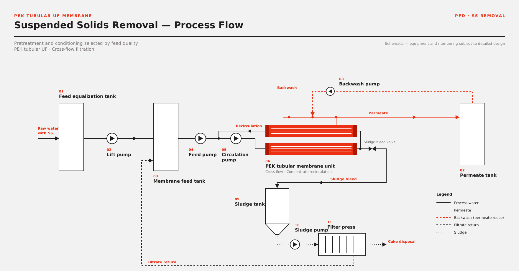
View the crawlable text process route
- 01 – Equalization and required pretreatment – Buffer flow and SS variation and provide screening, classification, or other protection for coarse particles, fibers, oil, temperature, or abnormal materials.
- 02 – Feed and cross-flow circulation – A feed pump sends material to the external tubular membrane loop. Hydraulic conditions depend on particles, viscosity, channel, and pressure drop.
- 03 – Tubular membrane solids separation – The PEK tubular membrane retains suspended solids and colloids within the selected separation range while permeate leaves the membrane section.
- 04 – Permeate enters downstream treatment – Route membrane permeate to buffering, reuse, NF/RO, resource recovery, or project-defined polishing.
- 05 – Concentrate and filtrate loop – Route concentrate to recycle, further concentration, or dewatering. Whether dewatering filtrate returns upstream depends on water quality and mass balance.
Core engineering principle:The tubular membrane physically separates particles from liquid. It does not automatically remove all dissolved organics, salts, hardness, heavy metals, or emulsified oil. Downstream stability still depends on complete water chemistry and process boundaries.

SOLID-LIQUID SEPARATION
State both what is retained and what is not removed
This page helps engineers understand the tubular membrane separation duty rather than extending clarification performance into a treatment claim for every contaminant.
- Particle retention
- Membrane pore size and layer structure determine the range of suspended solids and colloids retained. Selection requires particle size, target permeate, and downstream requirements.
- Cross-flow control
- Circulation helps control particle accumulation on the membrane surface, but velocity, pressure, energy use, and flux must be established for the feed and system.
- Permeate boundary
- Water and passing small molecules enter the permeate side. Removal of dissolved salts, some soluble COD, or other small molecules depends on downstream treatment.
- Concentrate management
- Retained solids remain on the concentrate side and require recycle, concentration, dewatering, sludge discharge, or resource-recovery routing.
When the objective requires chemical softening, heavy-metal precipitation, emulsion breaking, or biological degradation, complete the corresponding reaction first and use the tubular membrane for solids separation.
ENGINEERING BOUNDARY
Use public data for screening; do not apply project data directly to a new duty
General source references, existing project operating data, and new-project guarantee values are different evidence levels. This page retains public screening references while stating the applicability conditions for each.
| Engineering item | Current public reference | Project-specific confirmation |
|---|---|---|
| Feed SS | Source material uses 30–50 g/L as a high-SS screening reference | Also review particle composition, size, colloids, viscosity, settling, compressibility, and concentration variation; one SS value is insufficient |
| Permeate turbidity | Public reference below 0.5 NTU in applicable designs | Define membrane specification, feed composition, sampling point, analytical method, operating state, and downstream equipment requirements |
| SDI15 | Public reference below 3 in applicable designs | Use as one NF/RO pretreatment criterion while still reviewing oil, organics, hardness, silica, microorganisms, and other fouling risks |
| Membrane flux | No universal design value | The 60–200 LMH project records apply only to the corresponding feeds and conditions; set new-project values from testing, cleaning, and design margin |
| System recovery | No universal guarantee | Affected by solids loading, concentration limit, dewatering-filtrate recycle, sludge moisture, and plant-wide mass balance |
| Cleaning and continuous operation | No universal cycle or configuration | Confirm cleaning chemicals, temperature, frequency, standby membrane trains, and any N+1 need against contaminants, operating hours, and maintenance window |
Formal technical documents must list design conditions, design values, guarantee values, analytical methods, sampling locations, stable operating period, concentrate boundary, and exclusions separately.
PROCESS ROUTE SELECTION
Determine whether reaction or biology is needed before selecting the solids-separation route
Direct clarification, post-reaction separation, and MBR biological solids separation all use tubular membranes but have entirely different upstream responsibilities. Route selection must begin with contaminant form.
Direct suspended solids removal
- Target
- Suspended particles and suitable colloids already present in the feed and retainable by the membrane.
- Core route
- Equalization and required protection, tubular membrane cross-flow clarification, permeate interface, and concentrate handling.
- Applicable objective
- Reduce SS and turbidity and protect reuse, NF/RO, or downstream polishing.
Post-reaction membrane separation
- Target
- Convert dissolved hardness, silica, fluoride, or heavy metals into solids by chemical reaction first.
- Core route
- Chemical reaction, crystal or precipitate formation, tubular membrane solids separation, and downstream conditioning.
- Applicable objective
- Use the PEK softening or heavy metals removal process solutions rather than applying this route directly.
MBR biological solids separation
- Target
- Separate active sludge and microorganisms from membrane permeate in a biological system.
- Core route
- Biological reaction, external membrane circulation, sludge return, and project-defined polishing.
- Applicable objective
- When biological organic conversion is required, select cross-flow, air-lift, or anaerobic MBR first.
If the fluid also contains oil, hardness, silica, heavy metals, or high COD, a multi-stage process may be required. High suspended solids alone does not justify omitting other reaction and treatment units.
SOLUTION SCOPE
Define the membrane loop, concentrate route, and site interfaces separately
The following supports preliminary assessment and detailed design. It does not mean every project automatically includes all pretreatment, dewatering equipment, civil works, installation, downstream systems, or plant-wide performance responsibility.
Core membrane-circulation section
- PEK tubular membrane modules, racks, feed, and cross-flow circulation pump sets
- Permeate, concentrate, discharge, and CIP circuits
- Pressure, flow, temperature, level, and other instrumentation and control interfaces
Optional engineering scope
- Equalization, coarse-particle protection, buffer tanks, and required upstream conditioning
- Concentrate tanks, sludge dewatering, filtrate return, and N+1 configuration
- Permeate buffering, NF/RO, resource recovery, or downstream polishing interfaces
Owner / EPC interfaces
- Civil tanks, buildings, site piping, and utilities
- Feed and permeate analysis plus final routing of concentrate and CIP waste
- Installation and commissioning conditions, plant-wide interlocks, discharge, and local compliance requirements
Final scope, membrane-separation guarantee, downstream-feed responsibility, concentrate boundary, design responsibilities, and interface conditions follow the mutually approved technical and commercial documents.
APPLICATION ROUTES
Define applications around particle risks and downstream objectives
The applications below can enter preliminary assessment, but cannot share one membrane specification, flux, recovery, cleaning cycle, or permeate parameter.
Semiconductor packaging grinding wastewater
Retain silicon powder, abrasives, and fine particles from grinding and cutting to establish clarification ahead of reuse or RO.
Photovoltaic wafer grinding wastewater
Assess where cross-flow tubular membranes can supplement or replace conventional fine filtration for broad particle distributions and colloidal-silica risk.
Automotive coating and water-based cleaning waste
Clarify paint sludge, resins, and particles first, then connect to NF or other treatment according to solvents, surfactants, and resource-recovery objectives.
Industrial reuse and NF/RO pretreatment
Control SS, turbidity, and colloid risk while also assessing oil, organics, hardness, silica, and biological fouling.
High-solids resource-recovery streams
Design clear-liquid and solids-concentration routes separately to support filtrate reuse, solids dewatering, or material recovery.
Fermentation and process-fluid clarification
Route cells, proteins, fibers, and colloidal process fluids to process-fluid separation for separate assessment against product yield and purification objectives.
PROJECT EVIDENCE
Support preliminary screening with three real feed types and corresponding operating records
Customer names remain anonymous. Influent, effluent, membrane flux, and process combinations apply only to the corresponding projects and do not establish new-project design or guarantee values.

SEMICONDUCTOR PACKAGING GRINDING WASTEWATER · PUBLIC PROJECT RECORD
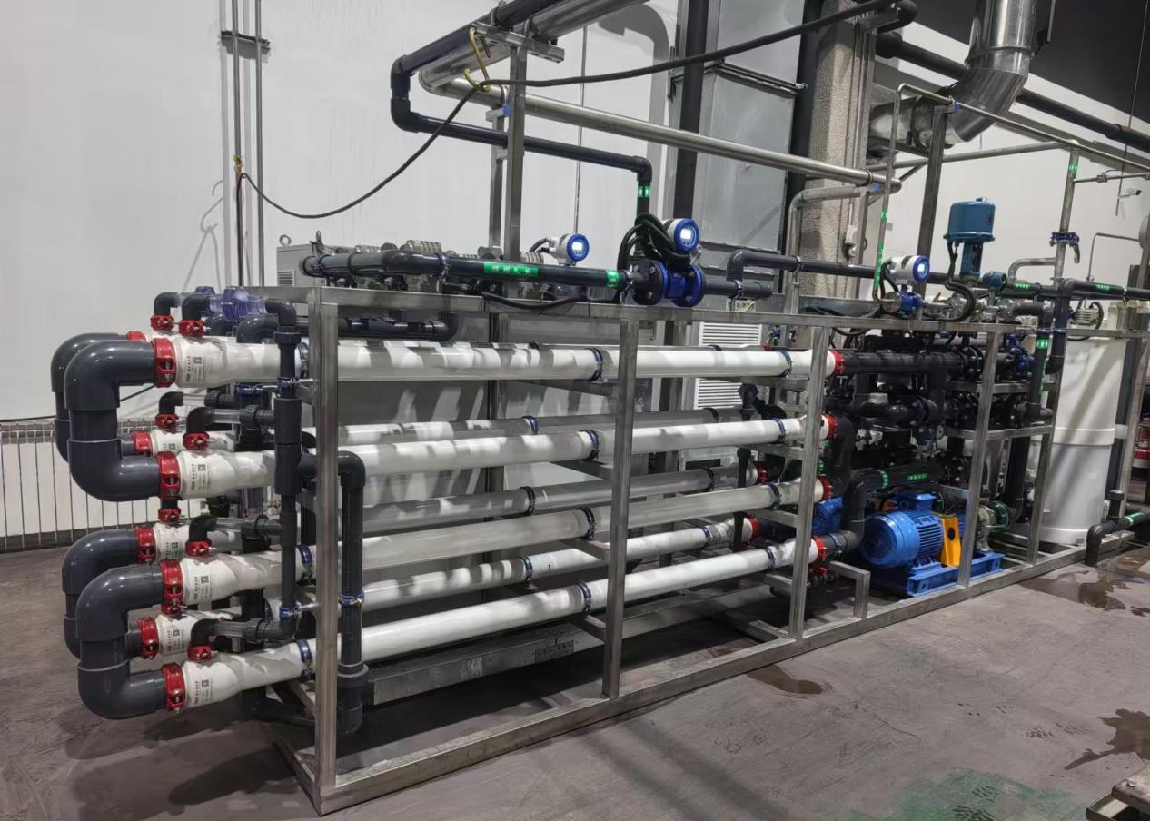
20 m³/h clarification and impurity-removal project at an anonymous Shenzhen company
- Influent
- SS 300–500 mg/L
- Effluent
- SS ≤1 mg/L as the RO pretreatment condition for this project
- Membrane section
- PEK tubular ultrafiltration cross-flow separation
- Reference flux
- 150–200 LMH; this project record only
PHOTOVOLTAIC GRINDING WASTEWATER · PUBLIC PROJECT RECORD
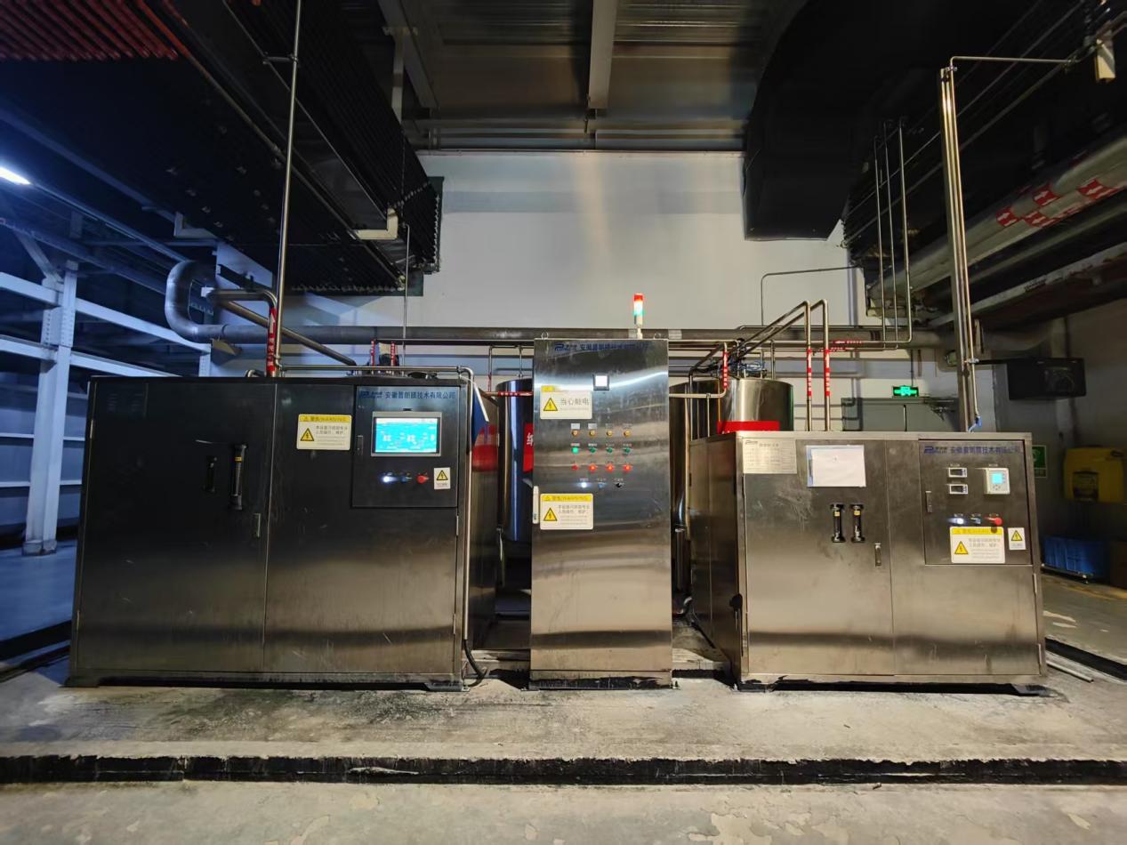
7 m³/h clarification and impurity-removal project at an anonymous Ningxia company
- Influent
- SS 300–500 mg/L
- Effluent
- SS ≤1 mg/L as the RO pretreatment condition for this project
- Retained material
- Grinding fines and colloidal silica
- Reference flux
- 150–200 LMH; this project record only
WATER-BASED CLEANING WASTE · PUBLIC PROJECT RECORD
0.4 m³/h resource-recovery project at an anonymous automotive company
- Influent
- SS 10,000–30,000 mg/L
- Effluent
- UF permeate SS ≤1 mg/L ahead of NF in this project
- Process combination
- Tubular ultrafiltration + nanofiltration
- Reference flux
- 60–80 LMH; this project record only
Project data comes from existing public material. Image-to-reference matching, complete process boundaries, sampling and analytical methods, image rights, and quantitative values require review before formal publication.
RESOURCES
Selection resources and next steps
ProductPEK tubular membrane details
Public resourceTubular membrane brochure
Project preparationProject evaluation worksheet
TECHNICAL FAQ
Suspended solids removal frequently asked questions
What does a tubular membrane mainly remove, and what does it not remove?
A tubular membrane primarily retains suspended particles and colloids matching the selected membrane specification. Removal of dissolved salts, some soluble COD, hardness ions, dissolved heavy metals, or small molecules depends on upstream reactions and downstream membrane or polishing treatment.
How does this process solution differ from MBR?
This route directly clarifies particles already present in the feed and does not perform biological organic degradation. MBR includes biological reaction and sludge return; the tubular membrane separates active sludge from membrane permeate.
Can coagulation, settling, sand filtration, or cartridges be removed after adding tubular membranes?
Not universally. The process may be simplified for particles suitable for direct membrane retention. Where destabilization, reaction precipitation, oil removal, or coarse-particle protection is needed, those units may remain necessary.
Can 30–50 g/L, turbidity below 0.5 NTU, and SDI15 below 3 be used directly as guarantees?
No. They are public screening references from source material. Actual applicability and permeate quality require particle composition, membrane specification, operating state, sampling method, downstream requirements, and project testing.
How is concentrate handled and how is water recovery determined?
Depending on the project, concentrate can enter recycle, further concentration, dewatering, resource recovery, or off-site handling. Plant-wide recovery must include sludge moisture, dewatering-filtrate return, CIP discharge, and other losses rather than membrane-section instantaneous flow alone.
What data is required for preliminary assessment?
Provide at least flow and operating hours, SS and turbidity with variation, particle-size or settling information, temperature, pH, viscosity, oil, COD, salinity, existing process, downstream objective, concentrate destination, and available cleaning conditions. Complex feeds should provide a sample or undergo bench testing.
TSS REMOVAL PROJECT EVALUATION
Submit particle loading and downstream objectives for preliminary route assessment
Upload water analysis, particle-size or settling data, existing flowsheet, and downstream feed requirements where possible. The engineering team will assess whether direct tubular membrane clarification fits, whether reaction or coarse-particle protection is needed, and how concentrate and downstream processes connect.
Submitted information is used only for preliminary project assessment. Final membrane specification, membrane area, flux, recovery, cleaning, treatment performance, scope, and guarantee conditions are defined in the formal technical documents.