
APPLICATION FIT
Review aerobic biology and air-lift circulation before confirming route fit
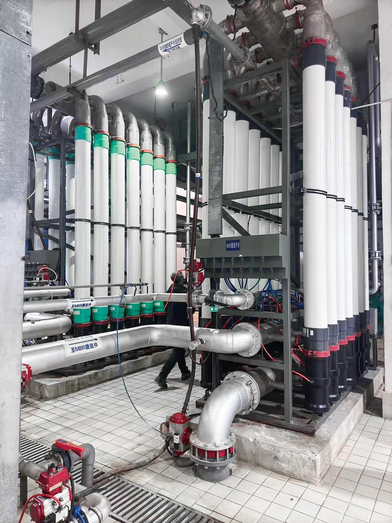
Air-Lift Tubular MBR injects air at the bottom to create gas-liquid lift, drive mixed liquor through external tubular membranes, and support membrane-surface scouring. It provides solids separation after aerobic biological treatment. It neither replaces biological reaction nor means ammonia stripping.
Suitable for initial assessment
Further confirmation required
- COD/BOD biodegradability, toxicity inhibition, salinity, fats and oil, foaming, and nutrient balance
- Biological oxygen demand, existing aeration capacity, air-lift blower conditions, and membrane-section gas-water distribution
- Sludge viscosity, filterability, temperature, pH, HRT, SRT, DO, and load variation
- Discharge, reuse, or downstream NF/RO objective plus site space, utilities, and sludge destination
- Influent load
- Flow, COD/BOD, ammonia nitrogen, total nitrogen, SS, oil, and variability
- Biological conditions
- Tank volume, MLSS, HRT, SRT, DO, temperature, pH, and salinity
- Air-lift conditions
- Blower, aeration layout, available air, membrane-train elevation, and circulation interface
- Treatment objective
- Discharge, reuse, polishing interface, and acceptable operating boundary
PROCESS ROUTE
Air injection, gas-liquid lift, and tubular membrane separation form a continuous loop
This is the basic route. Reactor zoning, feed arrangement, air distribution, membrane-train count, recycle location, CIP, and downstream interfaces require detailed design against project water quality, capacity, and site conditions.
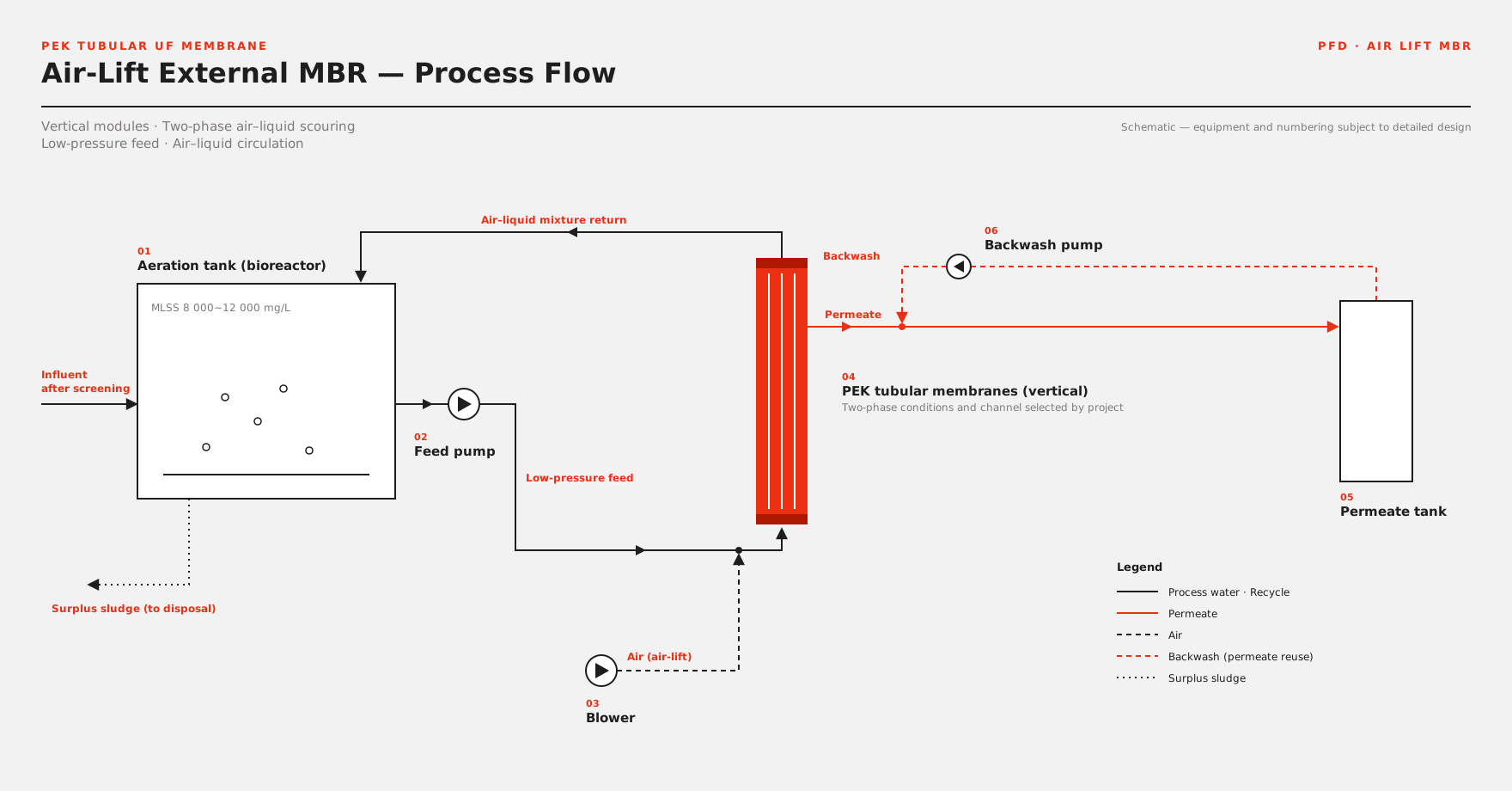
View the crawlable text process route
- 01 – Biological reactor – Convert organics and target contaminants under approved HRT, SRT, temperature, DO, and nutrient conditions.
- 02 – Membrane-section feed – Mixed liquor enters the external membrane section from the reactor. Feed, distribution, and upstream protection depend on sludge properties and layout.
- 03 – Bottom air injection – Distribute air from the bottom of the membrane modules to form two-phase flow with the mixed liquor and provide lifting force.
- 04 – Air-lift membrane separation – Gas-liquid mixed flow passes through open-channel tubular membranes. The membrane retains sludge and particles while permeate passes through.
- 05 – Permeate and sludge return – Route membrane permeate to collection or downstream treatment; return concentrated sludge to the biological system and waste sludge according to mass balance.
Key boundary:Lift air provides membrane-section circulation and scouring, but biological oxygen demand, membrane-section gas-water distribution, and blower capacity must still be calculated separately. One air condition cannot be assumed to satisfy every duty.
AIR-LIFT & SEPARATION
Define biological treatment, air-lift circulation, and membrane separation separately
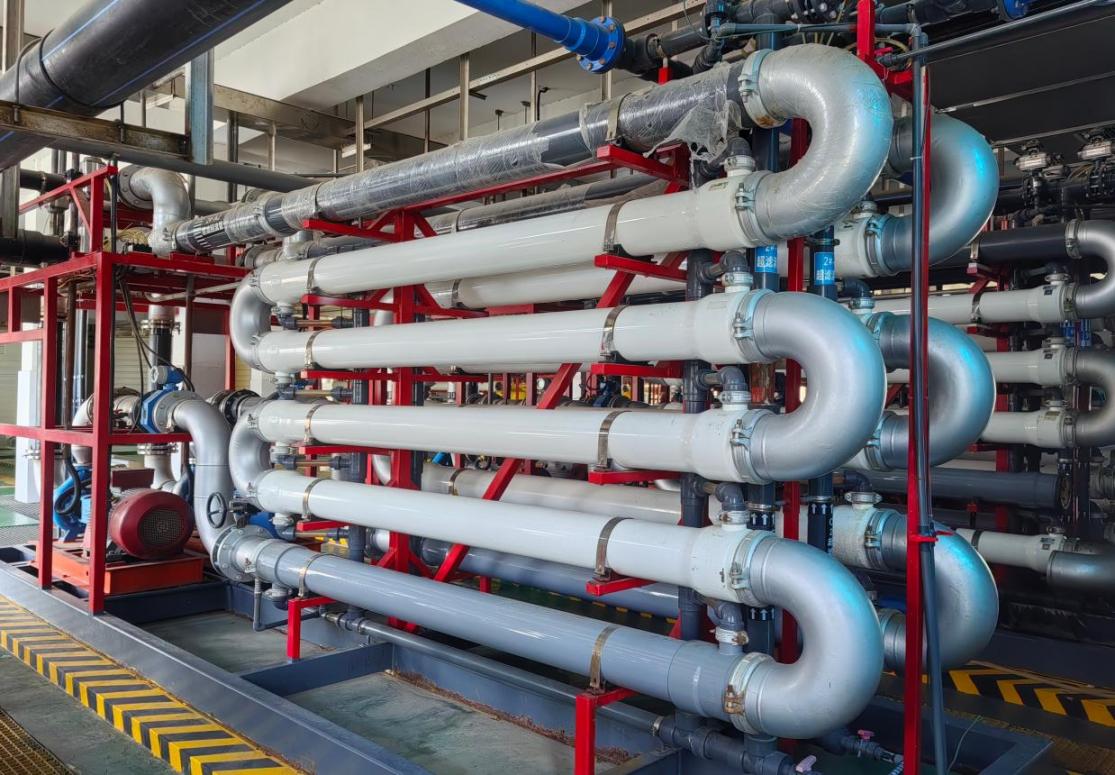
Air-Lift Tubular MBR performance comes from coordination of three functions, not one membrane element or blower parameter. Defining each responsibility clarifies the relationship among COD, dissolved oxygen, MLSS, membrane flux, and permeate parameters.
- Biological section
- Convert organics and target contaminants according to biodegradability, load, temperature, nutrients, and dissolved oxygen.
- Air-lift circulation
- Bottom air creates gas-liquid lift, drives mixed liquor through the membrane channels, and scours the surface. Air quantity and distribution depend on membrane trains and sludge condition.
- Membrane separation section
- Retain active sludge, suspended solids, and particles to maintain biomass and produce solids-separated membrane permeate.
- Downstream section
- Configure NF, RO, adsorption, oxidation, or other polishing according to discharge or reuse objectives.
Air-Lift Tubular MBR is not ammonia stripping. The former is a membrane bioreactor route with air-lift circulation; the latter is a separate physicochemical process that removes ammonia through gas-liquid mass transfer.
ENGINEERING BOUNDARY
Use 8–12 g/L only as a public screening reference
Brochure references, project operating records, and new-project guarantee values are different evidence levels. This page does not extrapolate project flux, energy use, effluent values, or cleaning cycles to other wastewater.
| Engineering item | Current public reference | Project-specific confirmation |
|---|---|---|
| Mixed-liquor MLSS | Air-Lift Tubular MBR public reference: 8–12 g/L | Set the actual window from sludge viscosity, filterability, temperature, salinity, biological load, and gas-liquid circulation |
| Air and lift conditions | No universal air rate or air-to-water ratio | Calculate biological oxygen demand, membrane lift and scouring, air distribution, blower margin, and system elevation separately |
| Membrane operating flux | No universal design value | Recorded flux applies only to the corresponding project; set new-project values from water quality, sludge, temperature, membrane area, and validation results |
| Membrane permeate and treatment performance | No universal COD, ammonia, or final-compliance commitment | Distinguish biological conversion, membrane solids separation, sampling point, analytical method, and downstream-treatment responsibility |
| Energy use and membrane life | No universal commitment | Affected by blower, feed, system scale, sludge properties, fouling load, cleaning, and O&M conditions |
| CIP and maintenance cycle | Defined by project | Confirm against contaminants, temperature, chemical compatibility, performance recovery, and site drain conditions |
Formal technical documents must list design conditions, design values, guarantee values, analytical methods, sampling locations, assessment period, air-system boundaries, and exclusions separately.
MBR ROUTE SELECTION
Cross-flow, air-lift, and anaerobic MBR serve different engineering conditions
The three routes are not simple tiers. Selection must consider biological process type, MLSS, sludge properties, circulation driving force, biodegradability, energy conditions, and resource-recovery objectives together.
External Cross-Flow Tubular MBR
- Biological process
- Primarily aerobic or project-defined biological treatment with external pump-driven cross-flow circulation.
- Screening profile
- High MLSS, high load, high suspended solids, or significant feed variability.
- Public reference
- MLSS 12–40 g/L; other parameters are project-specific.
Air-Lift Tubular MBR
- Biological process
- Aerobic biological treatment combined with external tubular membrane separation driven by gas-liquid lift.
- Screening profile
- Moderate MLSS where air-lift circulation may match system hydraulics and sludge conditions.
- Public reference
- MLSS 8–12 g/L; aeration, circulation, and membrane area are project-specific.
Anaerobic Tubular MBR (AnMBR)
- Biological process
- Anaerobic reaction combined with external tubular membrane separation.
- Screening profile
- High-strength biodegradable organic wastewater and resource-recovery objectives such as biogas.
- Key confirmation
- Organic loading, toxicity, temperature, biogas use, membrane circulation, and downstream nitrogen removal.
Final route selection may require sludge-filterability testing, water-sample testing, or pilot validation and cannot rely only on industry name, COD, or one MLSS value.
SOLUTION SCOPE
Define the membrane section, air system, biological system, and site interfaces separately
The following supports preliminary assessment and detailed design. It does not mean every project automatically includes all equipment, civil works, installation, or plant-wide performance responsibility.
Core air-lift membrane section
- Tubular membrane modules, racks, feed, and gas-liquid distribution interfaces
- Bottom air injection, permeate, recycle, discharge, and CIP circuits
- Pressure, flow, air, level, and other instrumentation and control interfaces
Optional engineering scope
- Blower and aeration system, biological-tank review, and sludge return
- Equalization, pretreatment, CIP, dosing, and automation
- Downstream NF, RO, reuse, or polishing interfaces
Owner / EPC interfaces
- Civil tanks, buildings, site piping, and utilities
- Sludge disposal, chemical storage, CIP-waste routing, and noise control
- Local standards, safety requirements, installation, and plant-wide interlocks
Final scope, biological-performance responsibility, membrane-separation guarantee, air-system boundary, design responsibilities, and interface conditions follow the mutually approved technical and commercial documents.
APPLICATION ROUTES
Select applications around aerobic biology, sludge properties, and load variation
The industries below can enter preliminary assessment, but cannot share one MLSS, air rate, flux, energy use, cleaning cycle, or treatment performance.
Industrial-park mixed wastewater
Review equalization, biological oxygen demand, sludge filterability, and air-lift membrane redundancy for mixed sources and shock loads.
Tobacco-industry wastewater
Configure the route around COD and SS variation, refractory components, aerobic treatment, and reuse or discharge objectives.
Mixed chemical wastewater
Identify toxicity inhibition, salinity, and biodegradability before defining biological load, air-system, and membrane-separation boundaries.
Food and beverage wastewater
Configure biology and the air-lift membrane section for organic load and batch variation, with attention to fats, temperature, foaming, and cleaning conditions.
Pharmaceutical and fermentation wastewater
Review inhibitory components, nutrient balance, and batch discharge; confirm suitability by water or sludge testing where required.
Aerobic-system upgrade
For existing systems where conventional settling is limiting and biomass must be retained ahead of reuse or polishing.
PROJECT EVIDENCE
Support preliminary screening with real capacities and duty-specific records
Customer names remain anonymous. The COD, MLSS, membrane permeate, and recorded flux below apply only to each project and do not establish new-project design values, applicability, or guarantee conditions.

TOBACCO-INDUSTRY WASTEWATER · PUBLIC PROJECT RECORD
1,100 m³/d Air-Lift Tubular MBR at an anonymous Anhui tobacco plant
- Influent
- COD 500–3,000 mg/L; MLSS 8,000–10,000 mg/L
- Effluent
- COD below 100 mg/L; membrane-permeate MLSS below 1 mg/L
- Reference flux
- 30–50 LMH; this project record only
Site image for this project is not public
MIXED CHEMICAL WASTEWATER · PUBLIC PROJECT RECORD
500 m³/d Air-Lift Tubular MBR at an anonymous Anhui chemical plant
- Influent
- COD 400–800 mg/L; MLSS 6,000–8,000 mg/L
- Effluent
- COD below 100 mg/L; membrane-permeate MLSS below 1 mg/L
- Reference flux
- 40–60 LMH; this project record only
The second project records MLSS below the lower end of the 8–12 g/L public screening range, showing that project records and general screening references are not interchangeable. Image rights and quantitative values still require approval before formal publication.
RESOURCES
Selection resources and next steps
ProductPEK tubular membrane details
Public resourceTubular membrane brochure
Project preparationProject evaluation worksheet
TECHNICAL FAQ
Air-Lift Tubular MBR frequently asked questions
Is Air-Lift Tubular MBR the same as ammonia stripping?
No. Air-Lift Tubular MBR uses air to create gas-liquid lift, drive an external tubular membrane loop, and support membrane-surface scouring. Ammonia stripping removes ammonia through gas-liquid mass transfer and is a separate physicochemical process.
What do the biological process, lift air, and tubular membrane each do?
The biological system converts biodegradable contaminants. Lift air provides membrane-section circulation and scouring. The tubular membrane retains active sludge, suspended solids, and particles. Biological oxygen demand and membrane air-lift conditions still require separate calculation.
Can MLSS 8–12 g/L be used directly as the design range for every project?
No. It is only a public screening reference. The actual operating window must also consider sludge viscosity, filterability, temperature, salinity, biological load, gas-liquid circulation, blower capacity, and maintenance conditions.
Can project flux and effluent data be used directly for a new project?
No. The 30–50 LMH and 40–60 LMH records and the corresponding COD and MLSS data apply only to those projects. A new project requires actual water quality, sludge, analytical methods, sampling points, and validation results.
When should Air-Lift Tubular MBR be selected instead of cross-flow or anaerobic MBR?
Air-Lift Tubular MBR is generally assessed for moderate-MLSS aerobic duties where gas-liquid lift conditions are suitable. Cross-flow MBR emphasizes high MLSS and pump-driven external circulation. AnMBR serves high-strength biodegradable wastewater and resource-recovery objectives.
What data is required and what does the process solution typically include?
Provide at least flow and variation, COD/BOD, ammonia nitrogen, total nitrogen, SS, oil, salinity, temperature, pH, existing biological process, tank volume, MLSS, HRT, SRT, DO, aeration or blower conditions, and target water quality. The solution scope first defines tubular membranes, gas-liquid distribution, feed, permeate, recycle, CIP, instrumentation, and controls; other scope is project-specific.
AIR-LIFT MBR EVALUATION
Submit water quality, biological, and air-system data for preliminary Air-Lift Tubular MBR assessment
Upload water-analysis, existing flowsheet, biological operating records, and blower or aeration data where possible. The engineering team will assess biological suitability, air-lift circulation, membrane-separation boundaries, and whether sludge testing or pilot validation is recommended.
Submitted information is used only for preliminary project assessment. Final biological route, air system, membrane area, flux, energy use, treatment performance, scope, and guarantee conditions are defined in the formal technical documents.